
The Servo Interface is a flexible support for servo motors added to shark 1.22 or higher version. The interface is the union of a specific software library and a circuit board, connected by the standard serial port (RS232) to a S.Ha.R.K. machine. As result, a Real-Time control system for servo motors can be easily built and put in action. All these hardware/software components will be described inside this page.
Look at Software Interface webpage for the library description.
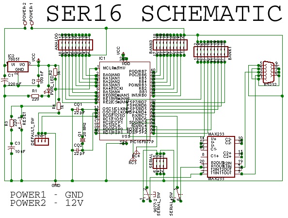
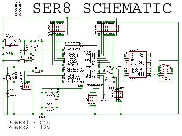
The interface circuit can translate the servo commands, sent through serial connection, to the servo control signal. Using a microcontroller (Microchip PIC) to elaborate these signals, we built an interface circuit that can support 8/16 servos simultaneously. The 8 servos version (SER8) uses a PIC16F876 (28 pins) microcontroller, the 16 servos version (SER16) uses a PIC16F877 (40 pins). (PIC16F873/4/6/7 Pdf Datasheet)
These kind of servos are driven by digital signals with usually 20 ms period. Anyway we added the possibility to change this value.
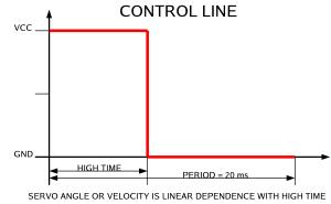
The HIGH_TIME is the control value. The servo library is projected to make this parameters invisible, and send command to a servo usign directly angle or velocity values (look at Software Interface).
The schematic of interface circuits (Download Eagle file ser8.sch ser6.sch).
<
| PINS BANK 0 | PINS BANK 1 | PINS ANALOG | PINS SERIAL | PINS I2C |
| 01,02 - GND | 01,02 - GND | 01,02 - GND | 01,02 - GND | 01,02 - GND |
| 03,04 - SERVO 00 | 03,04 - SERVO 08 | 03,04 - INPUT 00 | 03,04 - RX | 03,04 - SDI |
| 05,06 - SERVO 01 | 05,06 - SERVO 09 | 05,06 - INPUT 01 | 05,06 - TX | 05,06 - SCK |
| 07,08 - SERVO 02 | 07,08 - SERVO 10 | 07,08 - INPUT 02 | ||
| 09,10 - SERVO 03 | 09,10 - SERVO 11 | 09,10 - INPUT 03 | ||
| 11,12 - SERVO 04 | 11,12 - SERVO 12 | 11,12 - INPUT 04 | ||
| 13,14 - SERVO 05 | 13,14 - SERVO 13 | 13,14 - INPUT 05 | ||
| 15,16 - SERVO 06 | 15,16 - SERVO 14 | 15,16 - INPUT 06 | ||
| 17,18 - SERVO 07 | 17,18 - SERVO 15 | 17,18 - INPUT 07 |
The analog input is very useful for a feedback line,which carries information about the servo current consumption. Thw feedback line will be described inside the Power Circuit Section. The analog input is directly connected to A/D input PIC pins, the Software Interface has a specific function to read the sampled value of each input line. A LM7805 chip provides a stable voltage (+5 V), so the input voltage can be between 7 - 16 Volts. The control connectors are directly attached to the PIC pins. The PIC can drive two motors with the same line and usually the servos cannot be damaged by a wrong control signal. As default setting, when the circuit is powered or reset button is pressed, all the servos are turned off.
There are some dip switches on the schematic.
DEFAULT-SWITCH: If this switch is on, the PIC will start the servos following all default control values. These values are defined inside the PIC program. If the switch is off, the startup values will be the previously recorded ones, inside the PIC EEPROM. (look at Software Interface part)
SERIAL-SWITCHES: they are needed to jump the MAX233 chip and directly connect the serial line to the PIC serial pins.
The serial line is set to 8/N/1, and the speed is 19200 bps as default value. If a fast PC is used, it can be possible to set the speed to 115200 bps.
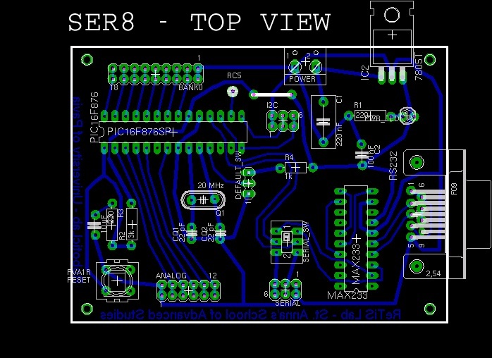
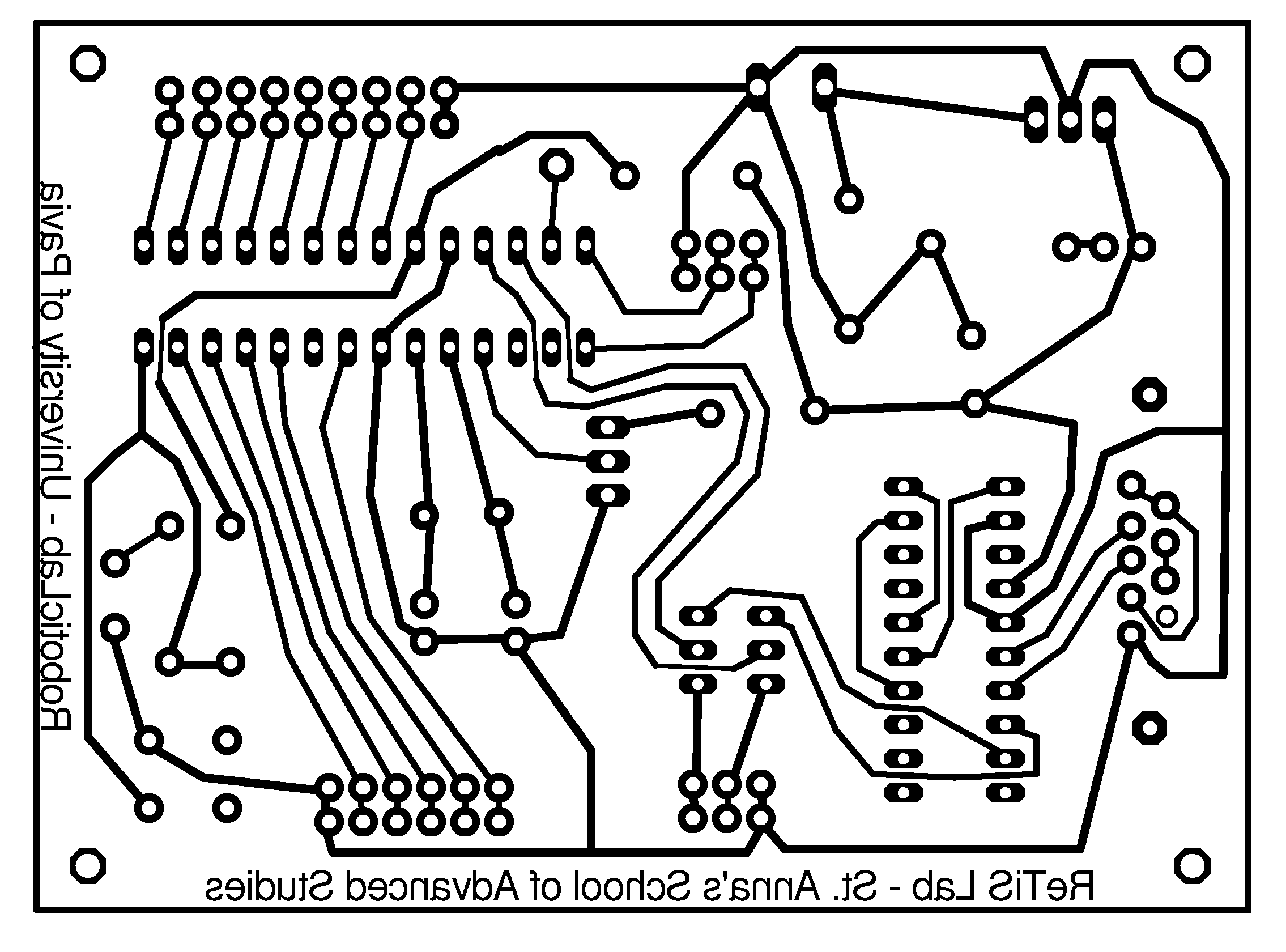
The PCB layout (Download Eagle file ser8.brd ser16.brd or 600 dpi bitmap ser8_600dpi.png ser16_600dpi.png)

Components List
SER8 INTERFACE | SER16 INTERFACE |
| 01 - 10 uF Electrolytic Cap. 16V | 01 - 10 uF Electrolytic Cap. 16V |
| 02 - 22 pF Ceramic Cap. | 02 - 22 pF Ceramic Cap. |
| 01 - 100 nF Ceramic Cap. 16V | 02 - 100 nF Ceramic Cap. 16V |
| 01 - 220 nF Ceramic Cap. 16V | 02 - 220 nF Ceramic Cap. 16V |
| 02 - 220 Ohm Resistor 1/4W | 02 - 220 Ohm Resistor 1/4W |
| 01 - 3.3K Ohm Resistor 1/4W | 01 - 3.3K Ohm Resistor 1/4W |
| 01 - 1K Ohm Resistor 1/4W | 01 - 1K Ohm Resistor 1/4W |
| 01 - Standard (0.5 inch) LED | 01 - Standard (0.5 inch) LED |
| 02 - Pin Headers 2x20 pins | 02 - Pin Headers 2x20 pins |
| 05 - Single DIP switch | 03 - Single DIP switch |
| 01 - Single button | 01 - Single button |
| 01 - Wago Screw Clamp (2 pin) | 01 - Wago Screw Clamp (2 pin) |
| 01 - OSC Crystal 20 MHz | 01 - OSC Crystal 20 MHz |
| 01 - Conn. RS232 Female | 01 - Conn RS232 Female |
| 01 - PIC 16F876 | 01 - PIC 16F877 |
| 01 - MAXIM MAX233 | 01 - MAXIM MAX233 |
| 01 - LM7805 | 01 - LM7805 |
The PIC program was developed with MPLAB:
Download 8 Servo Interface PIC16F876 program - source - HEX -
Download 16 Servo Interface PIC16F877 program - source - HEX -
Due to high current absorbed from medium and large size servo, a specific circuit is needed to separate the control section from the power one. There can be a lot of possible implemetation for a stable power supplier. A good solution is to use integrated chip like LM7806 or LM1084 to get a 5.5/6 Volt generator, which is a suggested value for normal servo operation
Inside the power circuit is possible to integrate a system to get the current consumption of the driven servo.
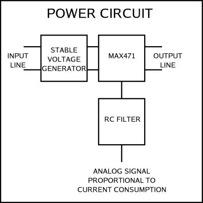
The Eagle schematic power.sch

A Maxim MAX471 is used to know the flowing current "Iload" from pins 2/3 to pins 6/7. The pin 8 generates a current I = Iload / 2000, so with a 2K load resistor there is a voltage V = Iload on pin 8. A RC filter is added because the servo consuption is impulsive and a low-pass filter is needed to get a value near the mean value. A feedback line is very useful to monitor the servo resistance and know if the servo reachs the right value of angle or velocity. The max current inside MAX371 is 3 amperes, so you must pay attention about what kind of servo you would like to monitor.